Turning an Altair 8800 Clone into a Micro-ATX PC
The Altair 8800 Clone
Computers have always, and will always, be a fascinating subject for me. When reading and researching computer history, the Altair 8800 is often part of the discussion. It is widely credited with sparking the "personal computer revolution" when it was released in 1975. The fact that this machine had to be built by the end user, its primitive I/O (switches and blinkenlights), and its historic significance spoke volumes. For many years I wanted to play with one.
A few summers ago, my best friend and I shared an apartment while we worked for the same company. Over many evenings we watched Mike Douglas's Altair 8800 instructional videos on YouTube. We would smile amongst ourselves when he would sign off each video with the same mantra: "The computer used in the demonstration today is actually an Altair 8800 Clone..." Those little plugs in the signoffs must have worked, because I bought one of them. It has been so great to hook up a "teletype" and run the Basic interpreter that gave Bill Gates and Paul Allen their start. I made it do 2+2 all in machine code (the answer was 4). I can't keep track of how many times I've died in Zork. And it's cool to see the origins of the A:/B:/C: drive lettering that all started in CP/M. In short, I've had a lot of fun with this machine.
There was another aspect of this clone computer that was intriguing. Although the Altair Clone website doesn't contain the message any more, at one time it said:
"Installation of a Micro-ATX PC Motherboard
The case of the Altair 8800 Clone is very under-utilized by the Clone's own hardware. For the fun of it, the empty
space in the cabinet is pre-drilled to accept a micro-ATX motherboard and a 3.5 inch hard drive. In addition, the
right AUX switch on the front panel is connected to a three pin header to allow its use as a power and/or reset
switch for the PC motherboard. A PC rear panel for the Clone may be manufactured in the future to accept a
standard PC power supply along with the motherboard's I/O panel and I/O slots."
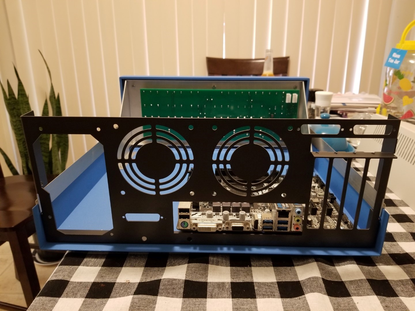
This is what I set out to do: Install a micro-ATX PC inside an Altair Clone. On YouTube, a fella by the name of Clint (better known as LGR) installed a micro-ATX motherboard in the clone's case sideways to make it fit. I decided to build the aforementioned rear panel and provide other accoutrements so the Altair Clone could contain a micro-ATX PC effectively, efficiently, and elegantly.
There were a few main goals for the project:
- The Altair 8800 functions must stay intact
- The case must have the least amount of mechanical modifications as possible
- The micro-ATX components must mount in the box like it was an off-the-shelf case
- The Altair and the micro-ATX must share a power supply and the two must be able to power on independently.
- Liquid cooling must be available for whatever processor gets put in the case
- Bulk hard disk space needs to be expandable
Designing a Rear Panel
To design a new rear panel, there were many tools at my disposal. The micro-ATX standard was indispensable. The cheapest micro-ATX case I could find and a pair of calipers were purchased. With a pen and a piece of paper, sketches started coming together to size the rear panel based on the Altair Clone case.
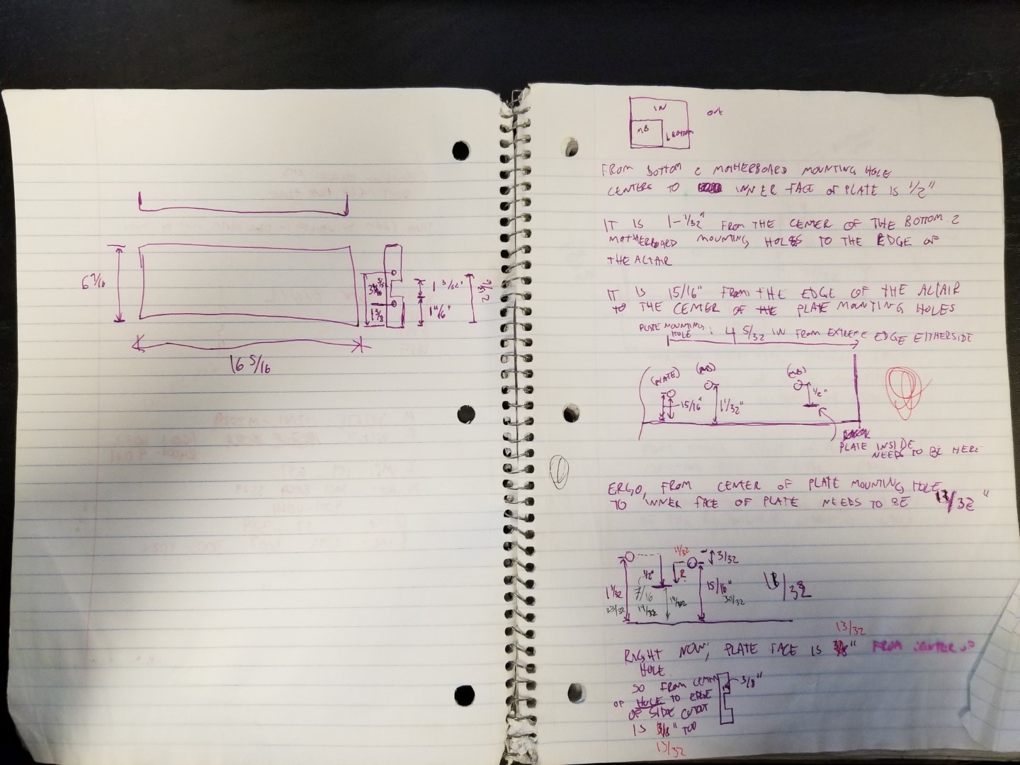
The initial chicken scratch.
Once the initial sketches were in place, CAD options for actual design were explored. Protocase, the fab shop that wound up stamping the panel, has a free tool for designing computer cases. Score. That tool was used to get the design in the ballpark.
Design work in progress.
There were a couple of things taken into account so the Altair Clone could stay functional:
- The optional Altair cassette interface needed somewhere to go
- The two serial ports of the Altair needed someplace to mount
Since the micro-ATX component placement was somewhat locked in place by the pre-drilled holes in the case, room for the cassette interface had to be found... somewhere. The ATX power supply cutout was moved as far to the side as possible until panel mounting screws started bottoming out. This opened up enough space between the power supply and motherboard for the cassette interface's DB-25 port. By standing the micro-ATX motherboard 20mm off the bottom of the case, enough room was made underneath the motherboard for the cassette interface circuit board (and as an added bonus, 20mm standoffs provided room for cable management). One of the 20mm standoffs was right in the way of one corner of the cassette interface's PCB, but there were no components here so it got trimmed. And it still worked.
Slight trim to the cassette interface
Originally a 120mm case fan had been aimed for. With the motherboard stood off the case 20mm to accomodate the cassette interface, there was even less room for a fan. This was a blessing though. Since the biggest fan that could fit vertically with the standoffs was 92mm, two could fit horizontally in the space above the motherboard. The two fans were spaced apart to fit an Asetek 545LC liquid cooler in one and a regular vent fan in the other. More on that later.
There was really only one place to put the two DB-25 cutouts for the serial ports -- above the PCI cutouts. This worked well, but it's kind of cramped.
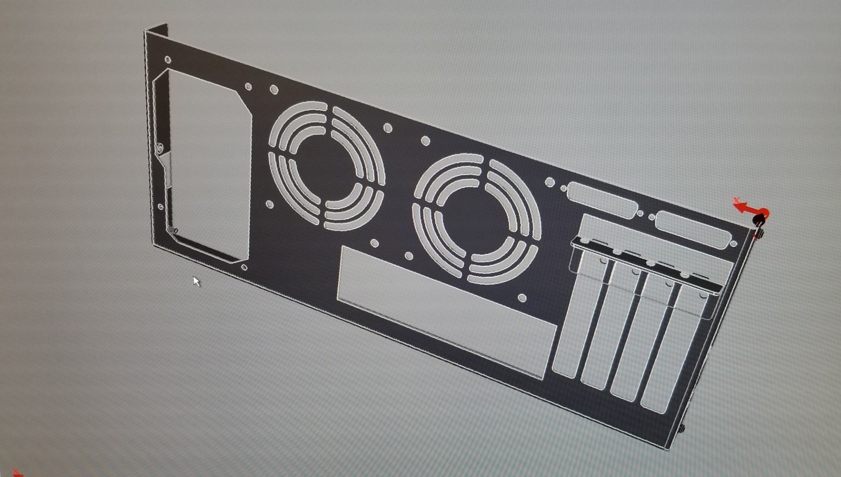
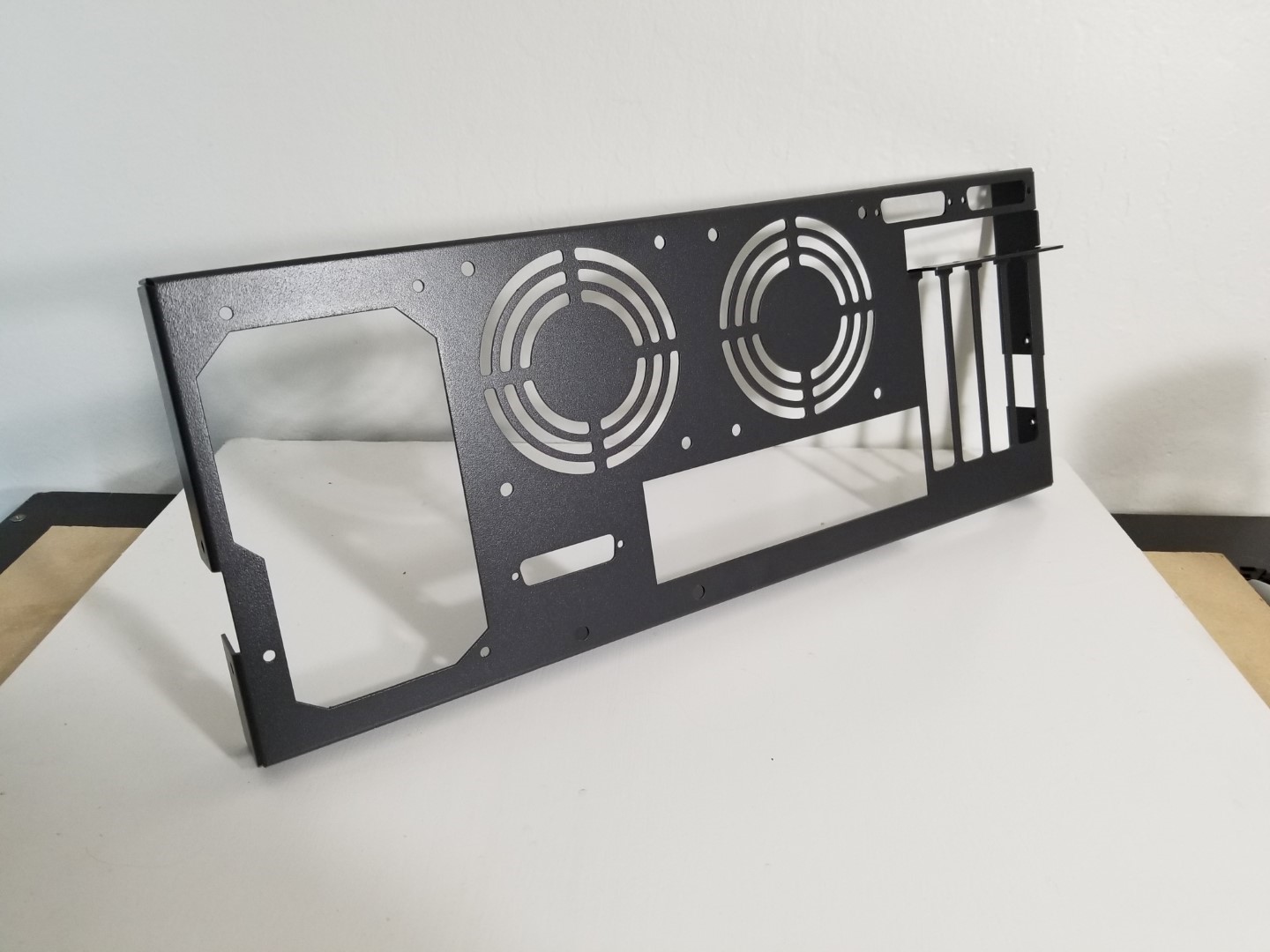
Once the design in the Protocase tool was to my liking, quotes were requested to have one made. It wasn't cheap! But the folks at Protocase were VERY helpful in getting the design exactly how I wanted it. And after months of tweaking and measuring, the first rear panel arrived. And amazingly, everything fit first try.
The finished protoype, fitting in a motherboard.
I called that first panel the "prototype", but it worked just fine. A few things were modified here and there (adding a lip on the top was the main thing, it was a little flimsy). Twice, orders of five were placed and they were put on eBay. They have since all sold. There are now ten of these backplates out there in the wild. The "prototype" sat around collecting dust for a few months, so I shipped it off to Clint (LGR) as a thank-you for the inspiration.
The final design.
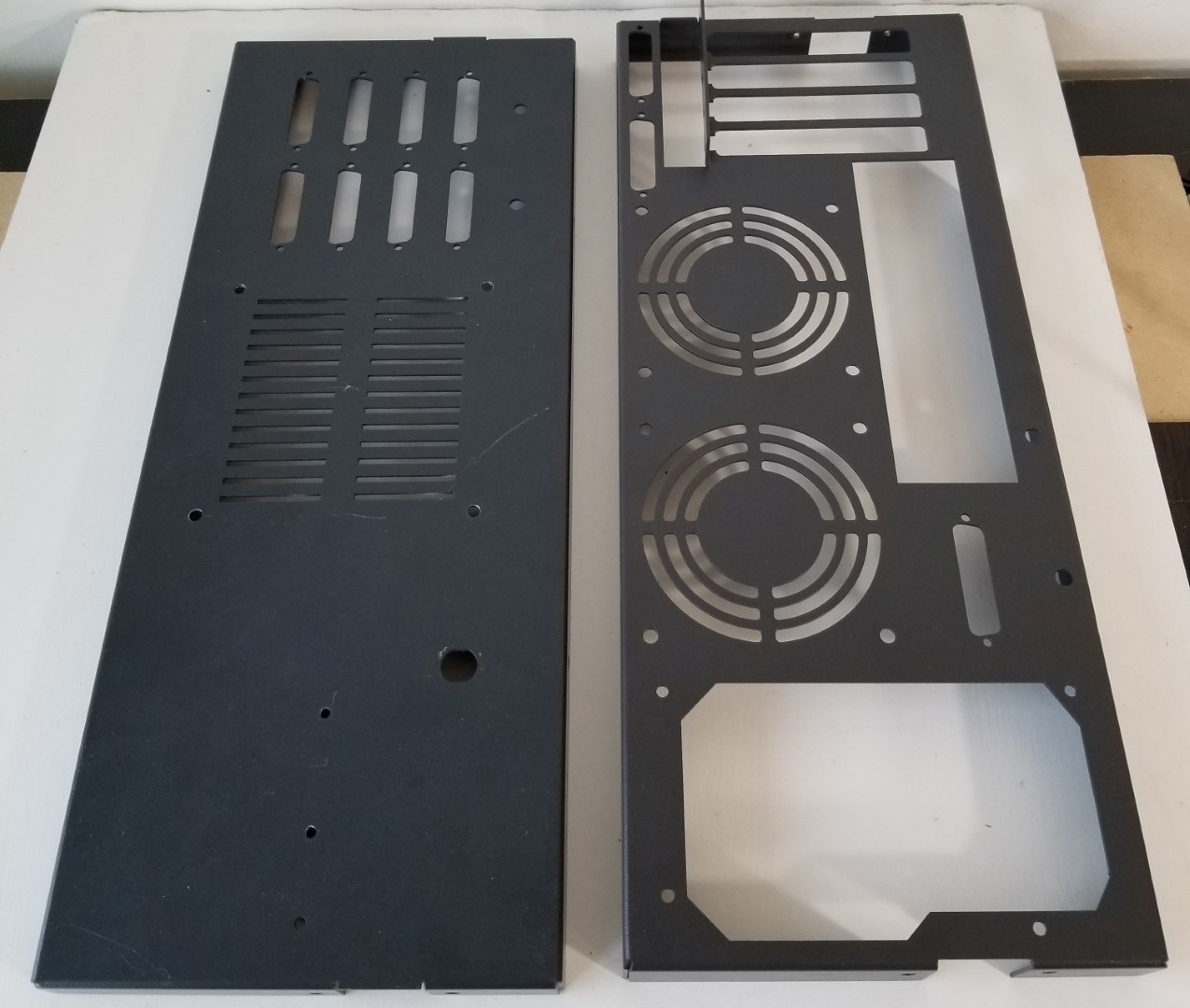
Original plate on the left. New plate on the right.
Power System
I wanted the micro-ATX motherboard and Altair Clone to share the same ATX power supply. A standard ATX PSU has a 5VDC line that is always on, regardless of whether the power supply is on or off. This "Standby Voltage", as it's known, was how I decided to power the clone. The clone came stock with a 12VDC power supply, so originally a 5V-12V buck converter was purchased to power the clone with the 12VDC that it needed. I shared this information on the Altair Clone forum, and was told there was a jumper that could be soldered onto the main board so it could be powered by 5VDC:
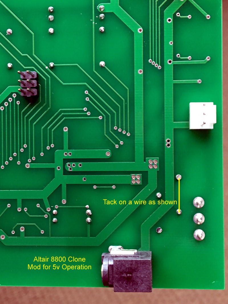
Courtesy Mike Douglas: Modification to power the clone with 5V instead of 12V.
With this modification, all that needed done was to tap the 5V standby voltage from an ATX Power supply to power the Altair Clone circuitry. Looking at the pinout, the standby voltage is +5VSB:
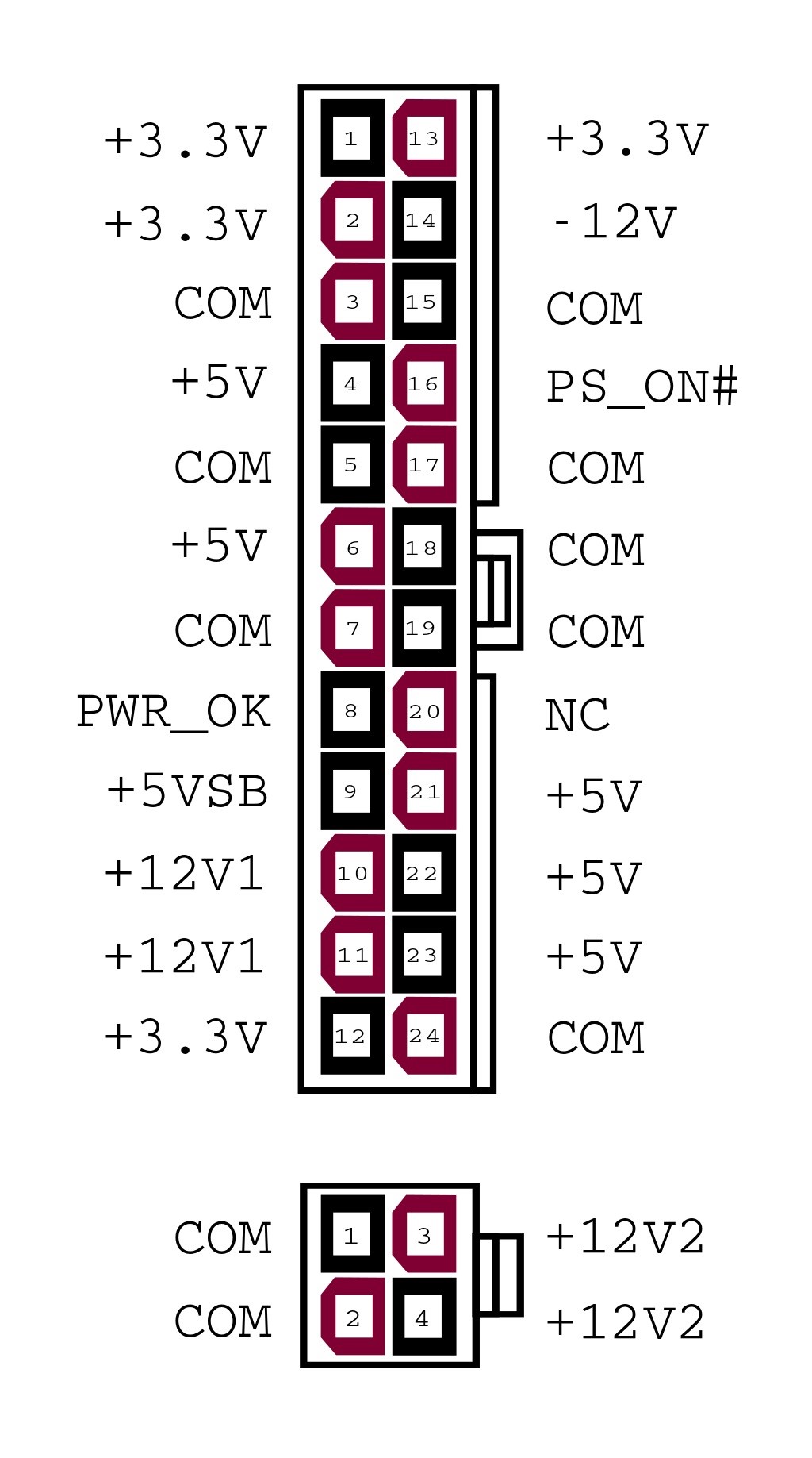
ATX power supply pinout
Some cutting, stripping, and soldering between the clone's stock power cable and the ATX Power supply, and the clone could be powered regardless of whether the rest of the power supply was on or off.
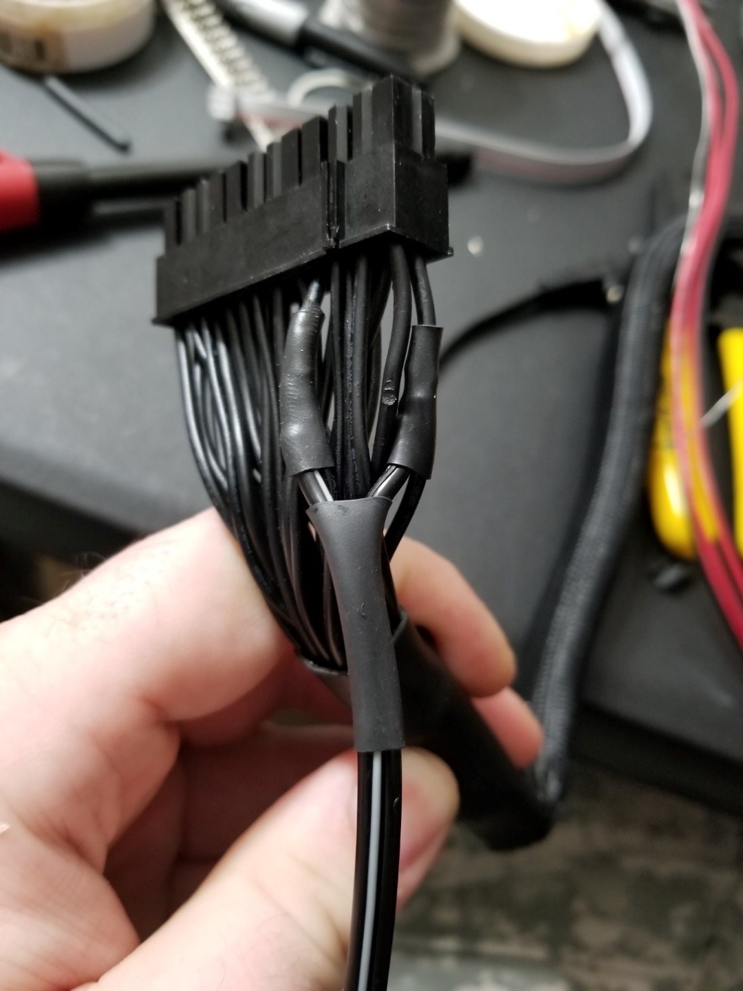
Tapping into the 5V standby voltage. Nevermind the iron nick and the fingerprints in the shrink tube...
With the clone powered, I needed a way for the switches on the Altair to turn the micro-ATX PC on and off. The Altair has two auxiliary switches, I'll call them AUX1 (left) and AUX2 (right), which went mostly unused back in the day. The clone was designed to have AUX2 power on and off the micro-ATX machine inside the case. Some ribbon cable was run from the AUX2 pin header to the micro-ATX motherboard and it worked just fine, but there was no feedback of whether the micro-ATX computer was running (aside from the whir of the fans) so I set out to find a solution. I looked around at Mouser and found some toggle switches that are about the same size as the switches on the front panel, but have an LED in the center of them. To make the LED switch work a few things had to be modified. The LED switch was much taller than the original AUX2 switch. So some of the LED switch base material was removed so it sat flush on the circuit board and lined up (close enough) with the rest of the switches when mounting to the front panel. Then I widened the holes in the circuit board that the original AUX2 switch mounted into and placed the LED switch on the board. I didn't worry about this being loose since the collar of the switch would anchor to the front panel and all of the wires would be soldered. The three pin header that was originally wired to the AUX2 switch was repurposed for a second 5VDC tap from the standby voltage with a couple wires run across the front of the circuit board, out of view. I had a switch and a feedback LED.
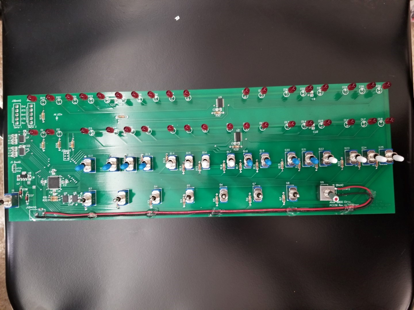
LED switch mounted with 5V run to the three pin header
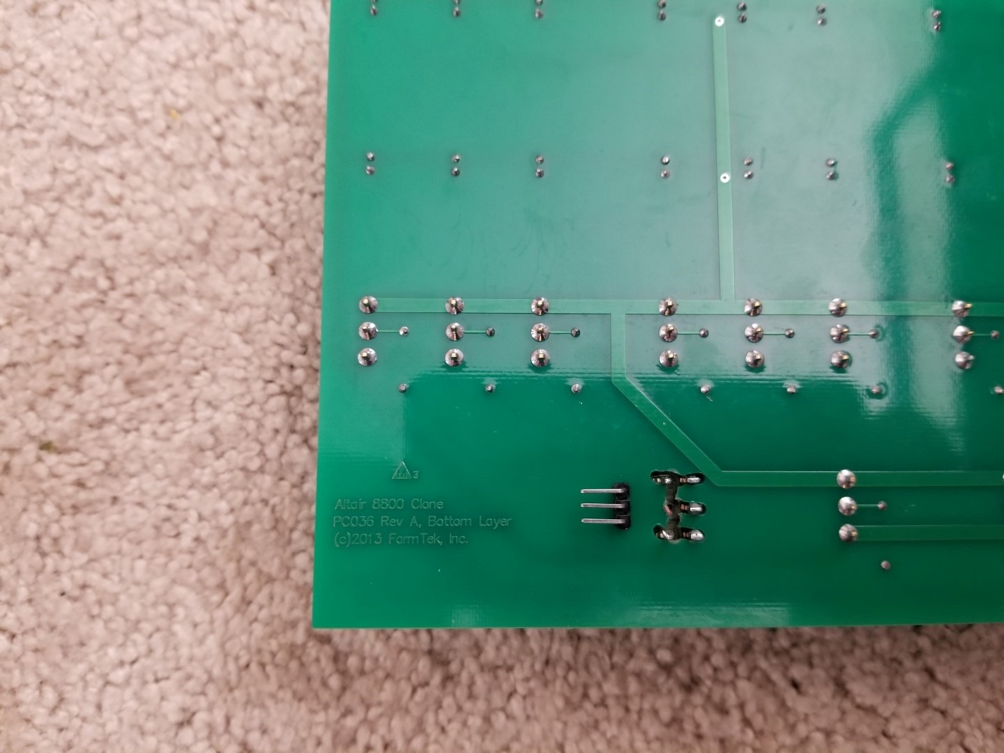
What the circuit board wound up looking like (from behind)
This was all fine and dandy, but unfortunately the only LED switches available were either ON-OFF-ON or ON-NONE-ON with no option for a momentary switch with a spring-return to center like the original AUX2 switch. So instead of wiring the switch directly to the motherboard, an Adafruit Feather M4 Express microcontroller (powered from that second 5V tap at the AUX2 pin header) and two 5V relays were installed. Both sides of the switch contacts (switch up/switch down) are inputs to the Adafruit. One relay coil is connected to the ATX power supply through a molex connector, and the relay contact is wired to an Adafruit input so the microcontroller knows if the ATX power supply is on or off. Code was written to use an output from the Adafruit to pulse or hold the second relay's coil when the computer is commanded to on, off, or sleep based on the position of the switch and the on/off status of the power supply. The contact of this second relay is connected to the micro-ATX motherboard where a regular power button would be. The LED pin from the motherboard was wired to the LED in the switch and everything worked great. The Adafruit and relays were mounted to a plate of 1/4" aluminum so no holes had to be drilled in the case. The aluminum plate is drilled and tapped to hold the Adafruit setup and to use the stock 3.5" HDD mounting holes in the Altair to anchor the aluminum plate to the case.
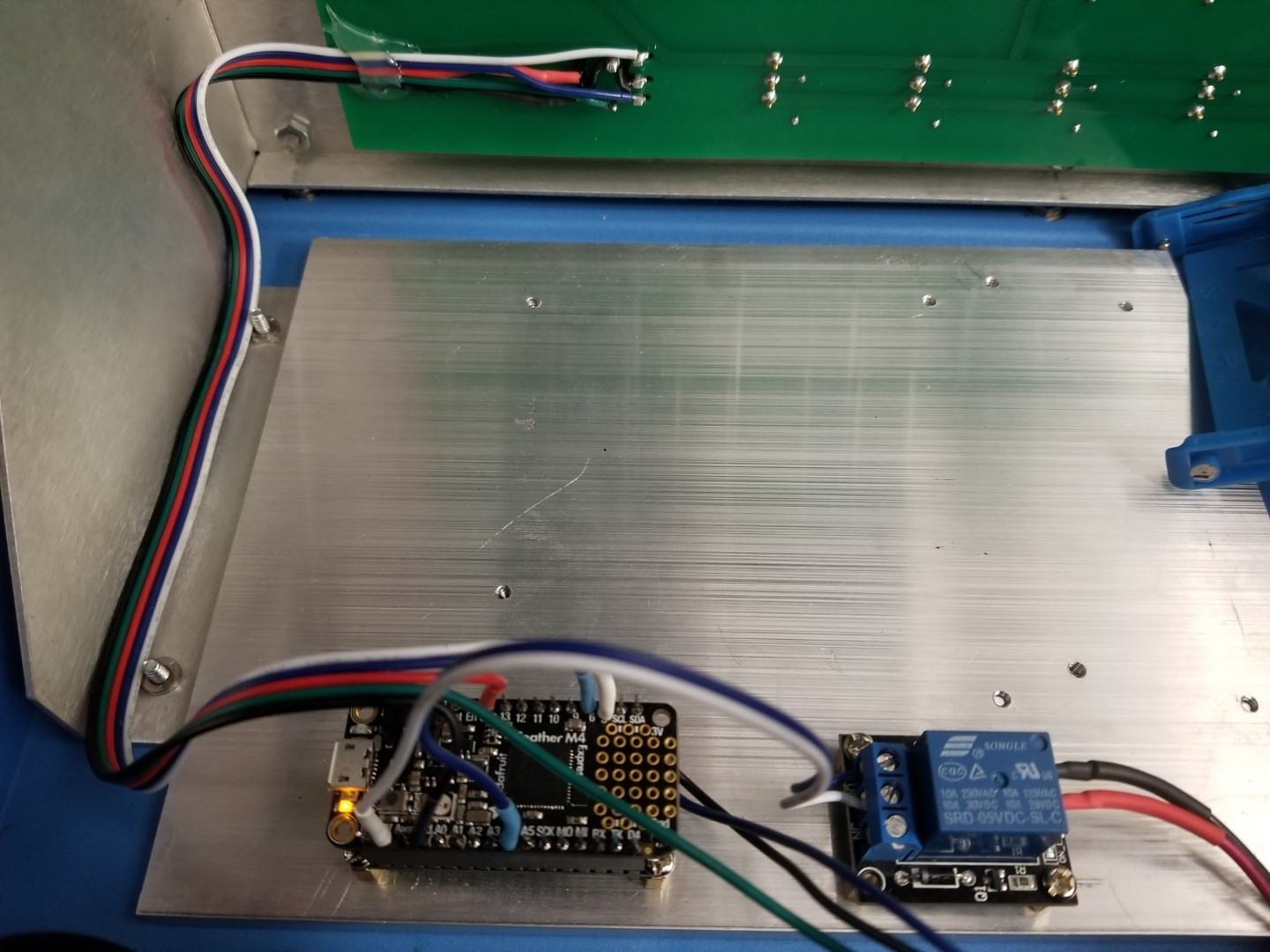
Adafruit and Relays mounted to the clone and wired to the new switch. The relay that pulses signals to the motherboard is under the Adafruit M4 mainboard
This part was an afterthought: With an Adafruit microcontroller handling turning the computer on and off, I decided to add an infrared remote control too. Because why not? I had extra Adafruit I/O pins and a spare IR remote laying around.
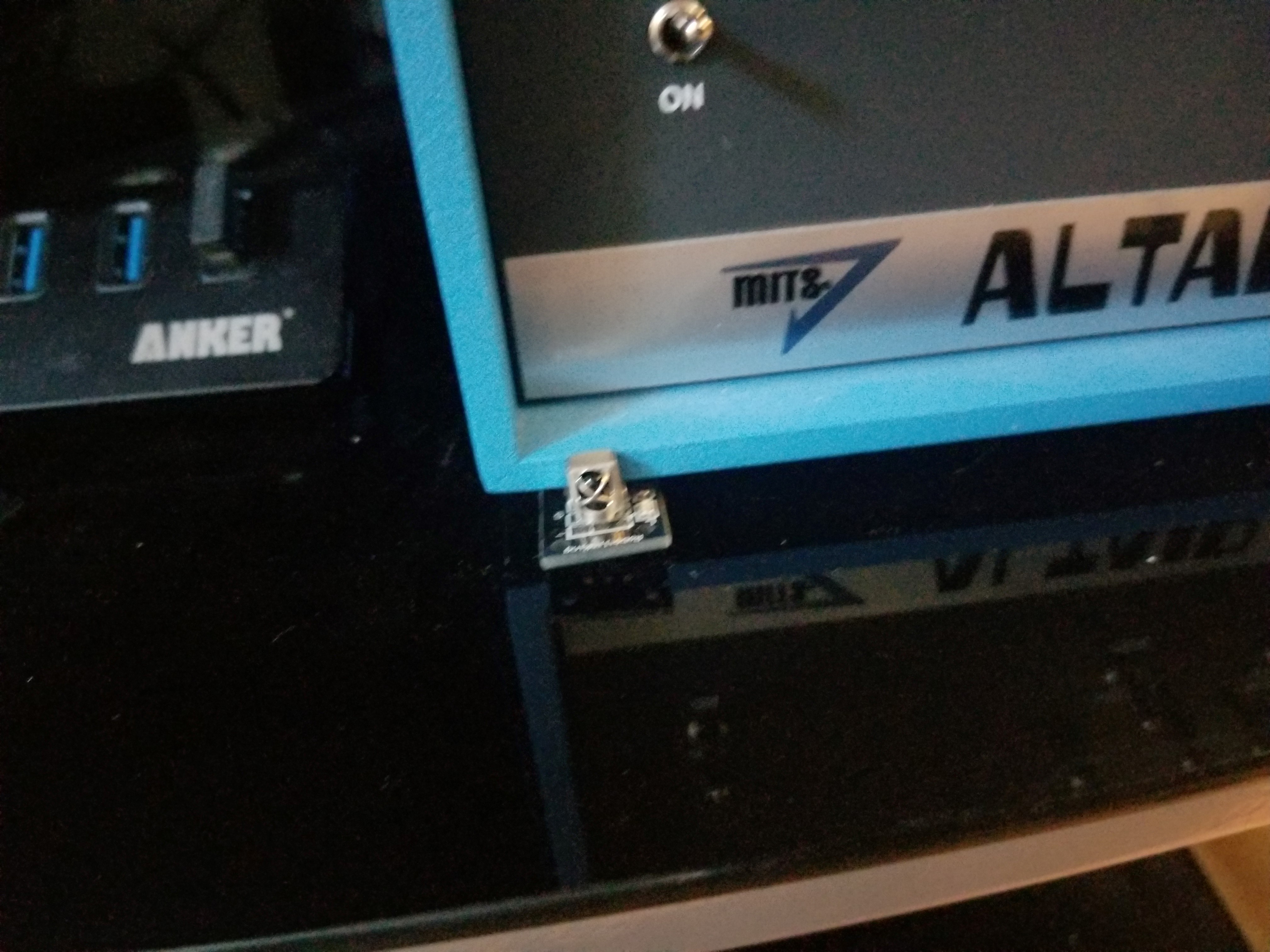
An IR receiver for turning the micro-ATX computer on and off from afar
When all was said and done, here's a sketched schematic of how the power system wound up.
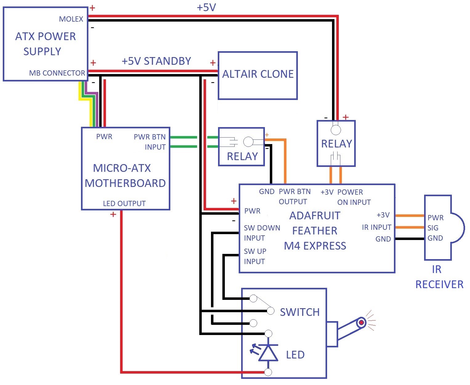
The power system in schematic form.
Cooling System
From the outset of the project, it was decided that whatever CPU was installed in the micro-ATX motherboard would need to be liquid cooled. As the rear panel design came together and 92mm fans became a strict design criteria, 92mm radiator options were investigated. There aren't many out there. One in particular, the Asetek 545LC, stood out as the best bet. It was an all-in-one and, more importantly, it had a small footprint (real estate on the rear panel was already hard to come by). I was able to find the dimensions of the cooler and spaced the 92mm fan cutouts on the rear panel accordingly. I purchased a 545LC and it fit beautifully in the cutout with a second 92mm fan beside it. This was not the permanent radiator, it got banged up quite a bit while fit testing. I had always planned on purchasing a second cooler for permanent installation.
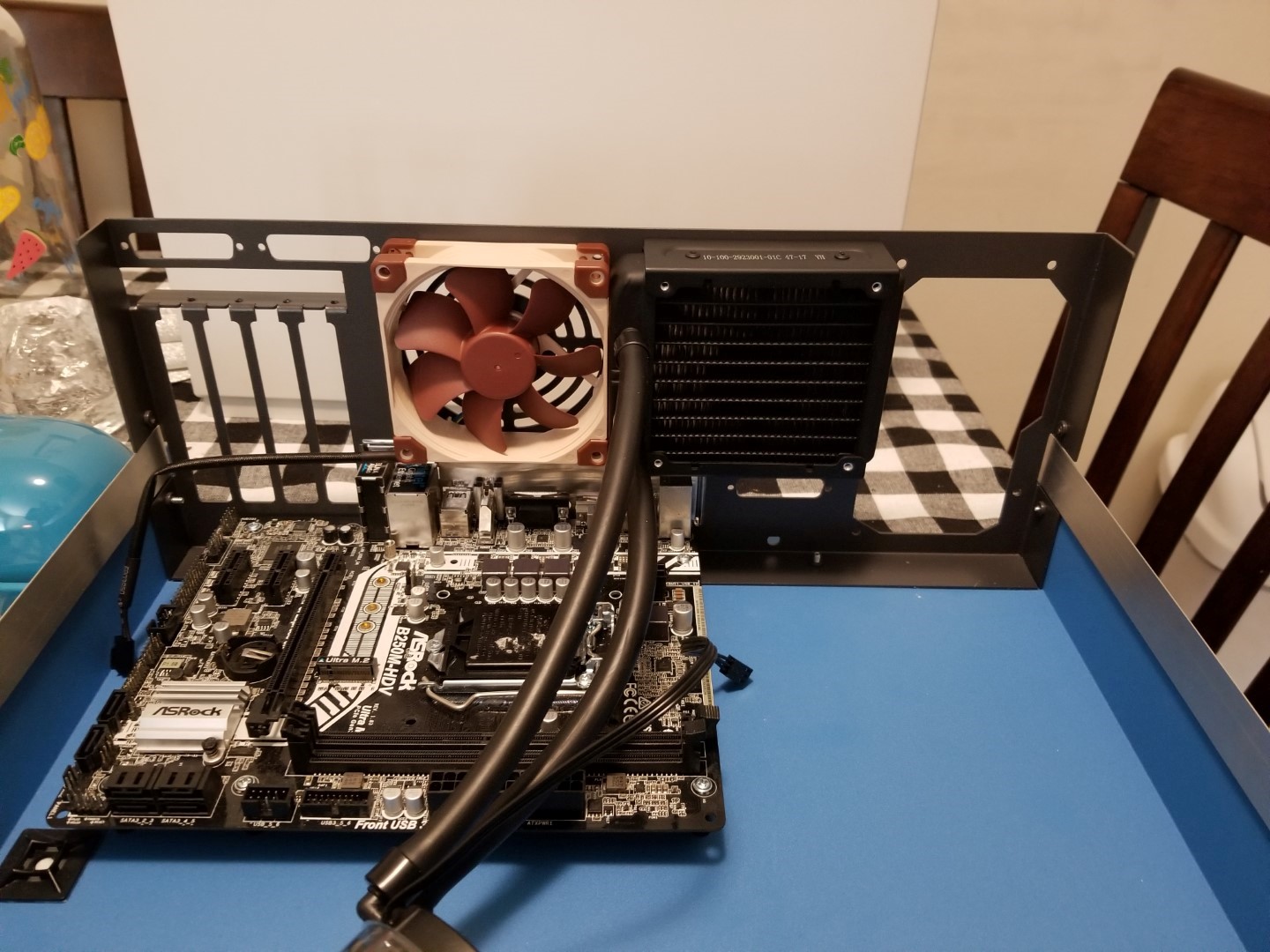
An Asetek 545LC radiator installed in the prototype rear panel
As the project wore on (it was worked on sporadically, not a high priority), at one point Asetek discontinued the 545LC cooler. I tried to fit some other 92mm radiator options inside, but the smallest other cooler I could find (a Black Ice Nemesis) is a comparative behemoth and required a separate pump and reservoir. It did fit, but I'm glad it didn't make it to the final design.
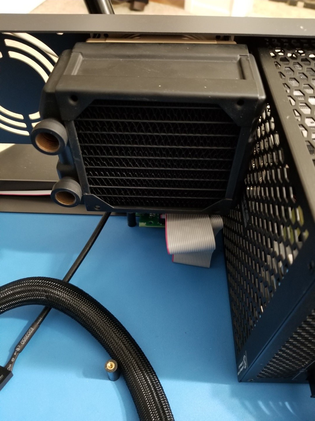
A Black Ice Nemesis 92mm radiator installed in the final rear panel. A very tight fit. Underneath is the cassette interface.
It had even gotten to the point of drilling and tapping the aluminum plate (with the Adafruit microcontroller installed on it) for the reservoir/pump combo and reducing the cold storage solution from 3.5" drive bays to 2.5" drive bays to make it all fit. This was not ideal. But it was all good. Six months or so after the discontinuation of the 545LC, Asetek announced they were building a follow-up, the 645LT. The footprint was exactly the same, but the pump was upgraded and the tube fittings on the radiator were replaced with 90-degree swivel fittings. I ordered the new cooler as soon as it went on sale, and its cooling my CPU at this very moment.
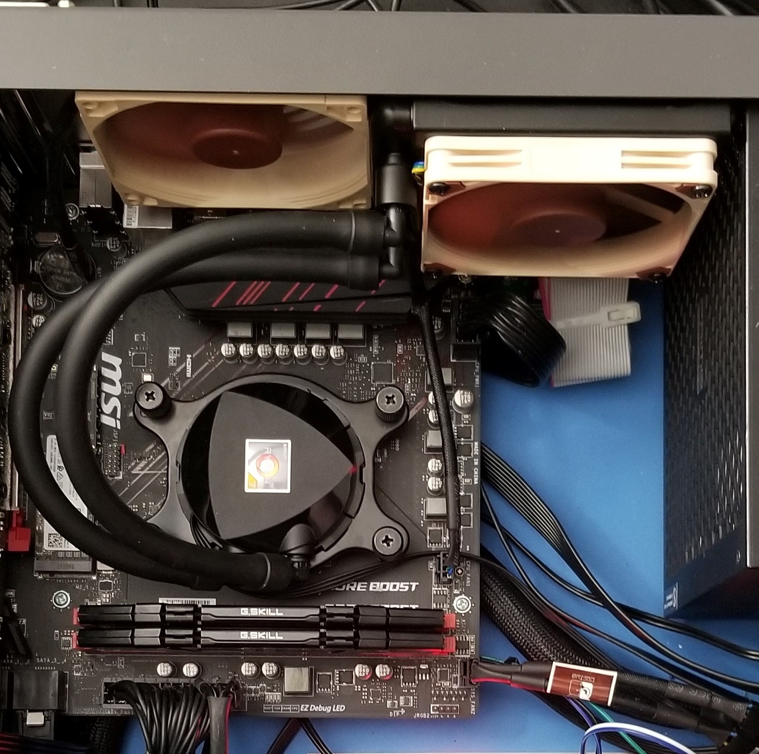
The final configuration of the cooling system.
Storage Solution
I'm somewhat of a data hoarder -- I have a folder worth of downloads that dates back to 2003. Every time I get a new computer, my files stay with me. I'm not *quite* ready to offload my storage needs to a cloud solution or a local NAS (network attached storage) yet. Old habits are hard to break, and I like having all of my files right here ready when I need them. So multiple disk drives needed to go in the Altair Clone.
On eBay, I found a (what may be used) 3.5" disk drive bay with removable plastic rails for installing and removing up to five disk drives. It even came with a 120mm fan to blow air over the installed drives.
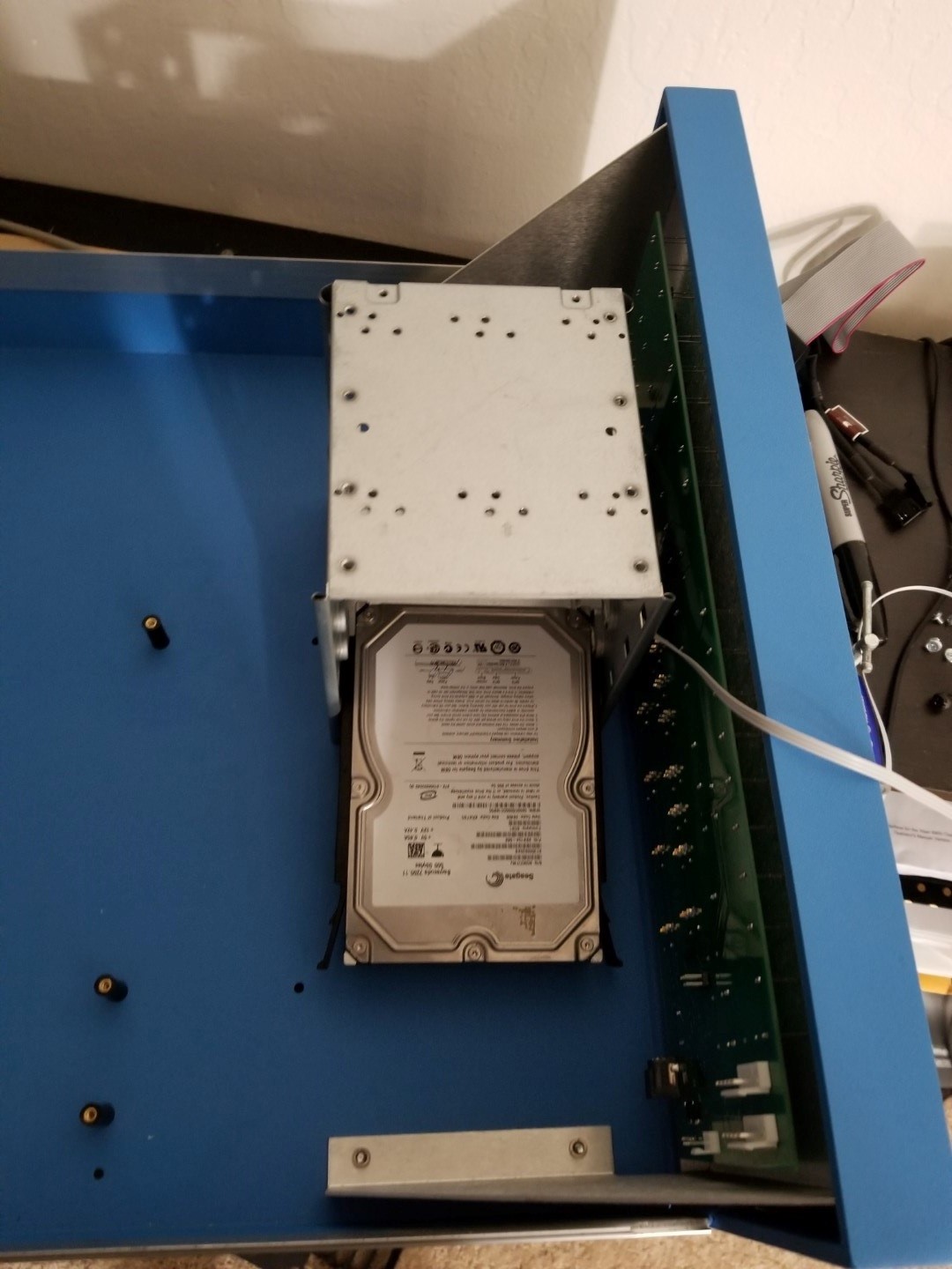
A - possibly used - disk enclosure solution
This drive enclosure was mounted on the same piece of 1/4" aluminum that the Adafruit Feather power managment microcontroller is mounted to. Moved all the way to the right (when looking at the front of the machine), there is *just* enough space to slide drives in and out with a large video card installed in the PCI slots. It is a little flimsy, the fan is a little loud, and the whole thing is kind of an eyesore, but other than that it works great. Three 6TB hard drives were installed. Two are for daily use, one is an archive (including that downloads folder from 2003). A 1TB M2 PCI-e SSD is the boot drive. These are just for hoarding.
Put Together
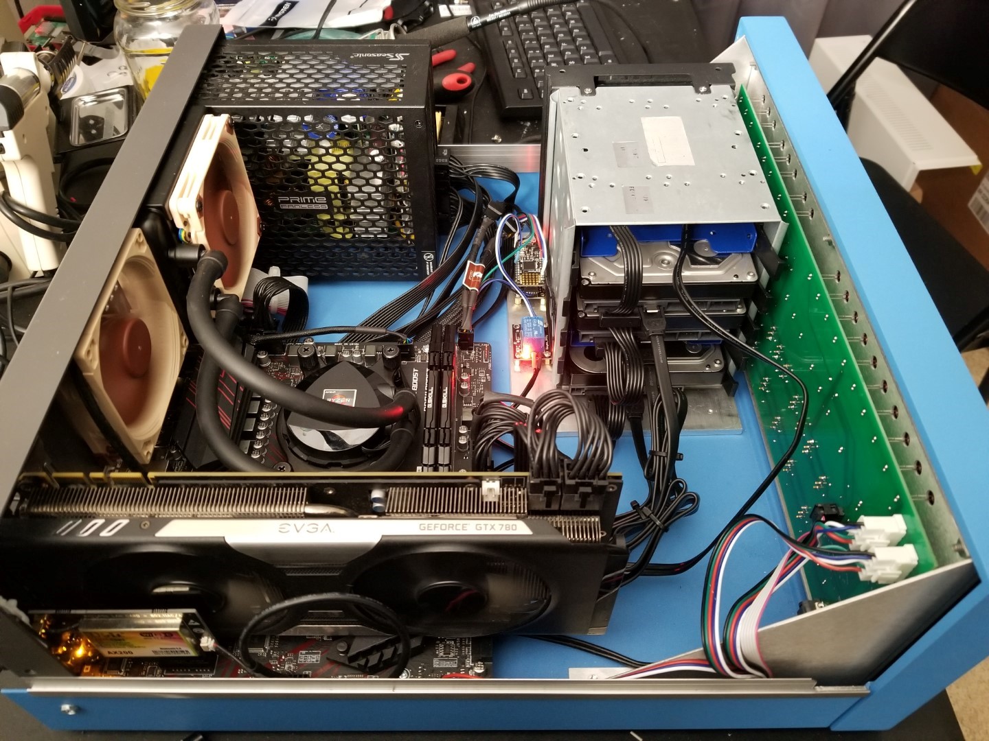
After many months, the Altair was finally ready for the micro-ATX equipment. Here it is just before all the modern stuff was installed:
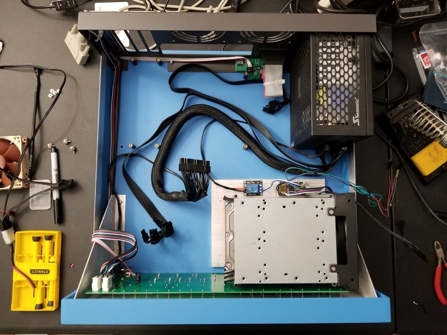
Ready for micro-ATX stuff.
- The Altair 8800 devices are all installed and working. The clone's serial cables and cassette interface ribbon cable have been extended to keep them out of the way.
- Except for the new power switch, no modifications were made to the Altair itself.
- The micro-ATX components are bolt-in... even if it's a tight fit in places.
- The Altair 8800 can be powered on and off independent of the micro-ATX machine.
- An Asetek 645LT liquid cooler is ready to install.
- There's five 3.5" drive bays to work with. Three are used. There's a fan to keep them cool if it does fill up and vent holes start to get covered.
A few orders from Newegg and the case had stuff in it:
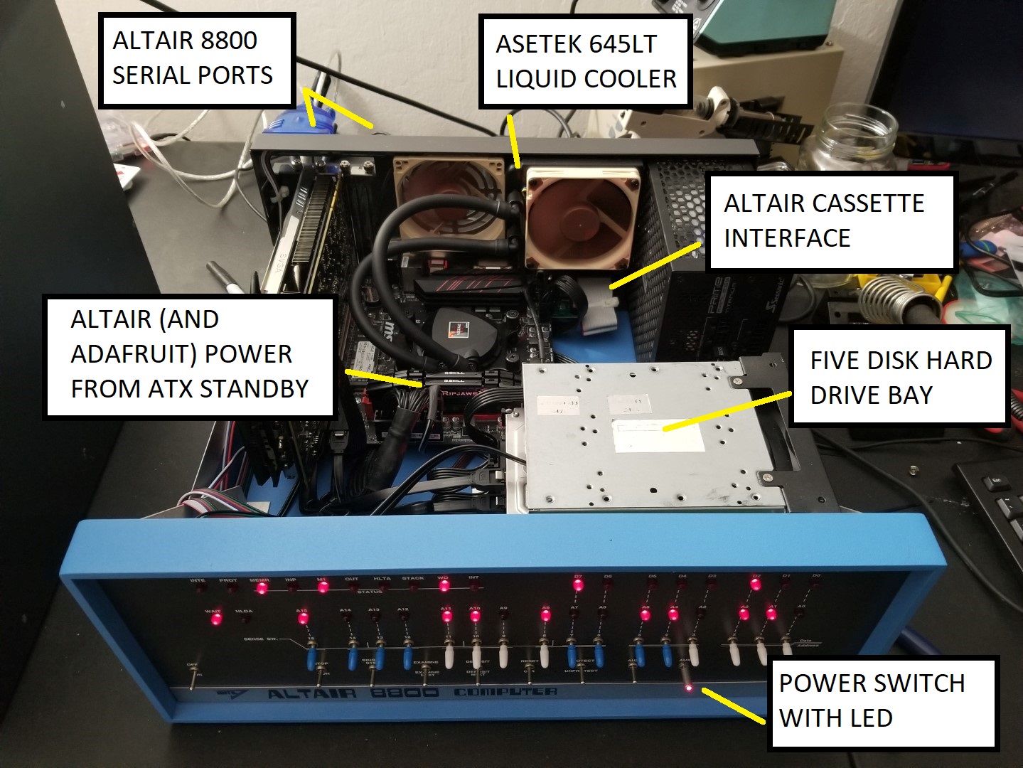
All goals met.
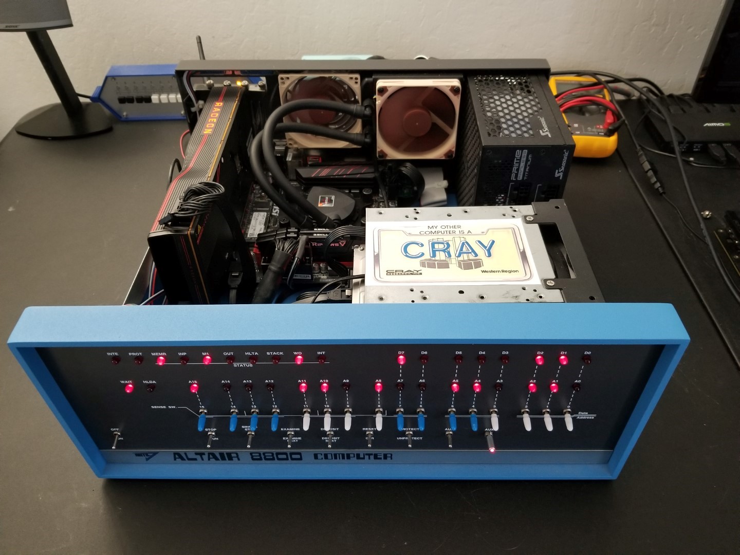
From another angle. The Geforce GTX 780 has since been replaced with a Radeon 5700XT.
I'd say this project was a success. I've had more fun with this Altair Clone than I could have ever bargained for. I'm not going to list the micro-ATX components since modern computer equipment is all cookie cutter and I'll probably be swapping things in and out regardless. I guess the only thing that matters is the processor is a Ryzen 2700 since it only had 65W TDP and I didn't know how the little Asetek cooler would keep up when I bought the processor. It kept up just fine. A 3-hr burnin with Prime95 and CPU-Z running stress tests it never rose above 64degC. But that's about it. Hope you enjoyed it! I sure did.
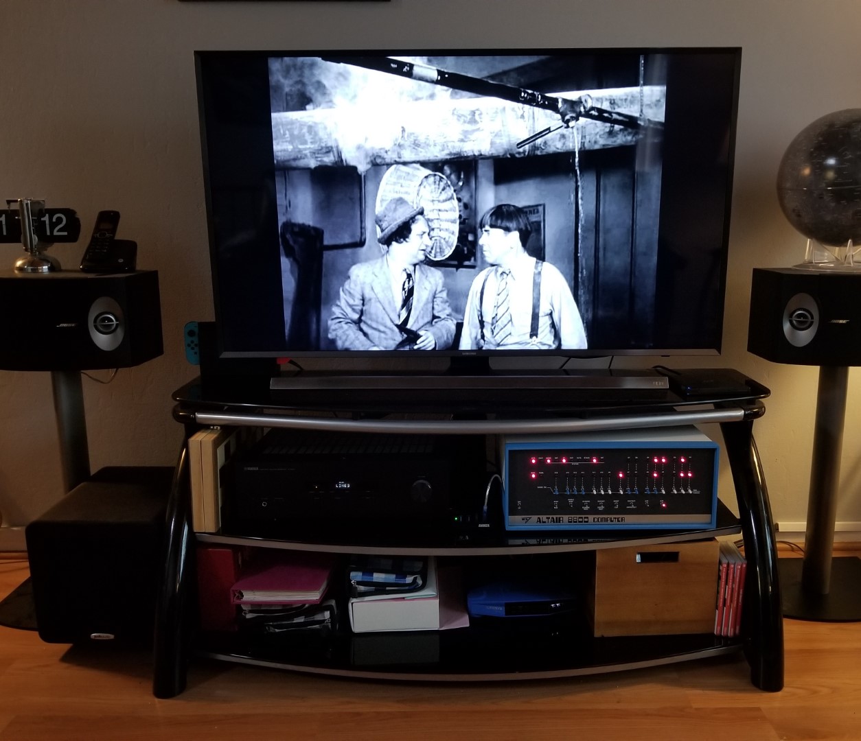
In its (old) home, doing its job. Since this picture was taken the Altair has been moved back to a desk so I can actually play with it.
Contact
Feel like dropping me a line? Be my guest: steve (at) cton.me